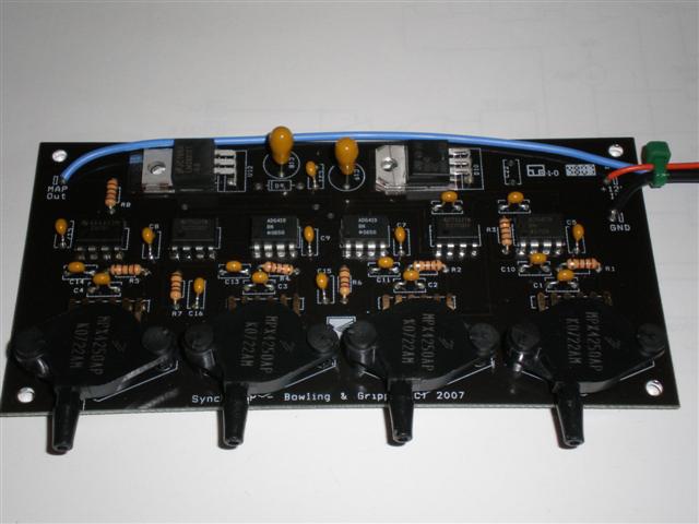
SynchroMAP™ is a small add-in board that allows MegaSquirt® to capture the lowest MAP signal from 4 MAP sensors. This is especially useful for those with individual throttle bodies (ITB).
SynchroMAP™ improves the range under which the speed-density based algorithm can operate efficiently, potentially avoid the use of alpha-N in some cases.
ITBs give highly erratic MAP signals at low rpm because the pistons are going compressing and sucking air and there is no plenum to smooth it all out. So when the processor samples the manifold pressure, it is seeing what is essentially a random MAP kPa from within the operating range and therefore setting fuel pulse widths that have a random component.
One problem with sampling only one ITB runner on a multi-cylinder setup and using this as an estimator for the other cylinders is that you cannot do accurate cycle-by-cycle fueling. MAP can change significantly from cylinder-to-cylinder for events like throttle transitions, etc. Controls like X-Tau and other model-based code require accurate mass air information for each intake event.
If you put a restriction in the line, this can delay things. The best way to smooth this out is to force sampling of the map at the same time in the stroke for each cylinder. So using the 'Injection Timing Delay' parameter variable may help by moving the sampling point to an more optimal time in the cycle. Users can experiment with it til they get the most consistent maps. If that smooths your idle enough then look at the full throttle, hi rpm case.
If there is still variation from cylinder to cylinder, this is likely because the processor isn't fast enough to sample the MAP consistently at high rpm. The synchroMAP does it through hardware that is way faster than you can ever rev. The big advantage of this is that the ultimate goal is to measure how much air is entering each cylinder. The most direct and accurate way is a MAF sensor, the next is to use map but sample consistently at intake closing as synchroMAP™ does. Using the throttle as an indicator of air flow, as in alpha-N, is the most indirect and inaccurate way. But if the differences aren't detectable or objectionable to the user, then that is fine. We can say that with Bruce's ITB test engine and synchroMAP™, MAP kPa at idle improved by a huge amount - see below.
Note that it is important to sample the MAP at the same point on the intake cycle, be it one MAP sensor or many. The idea of speed-density is to find out the mass of air and this is done by knowing the air density and the volume of the cylinder. The point where intake valve is no longer flowing air into the cylinder (i.e., it is closing). All of the codes do 'synchronous sampling' and MS-II™ variants can adjust this point.
The base MS-II™ code recomputes the fuel for each cylinder event. For example, if you have a 4-cylinder 4-stroke engine, with fictitious firing order 1,2,3,4, then there is one sample at, say crank 0 degrees (when cylinder 1 is at bottom), then next sample is at crank 180 degrees (cylinder 2 at bottom), then crank 360° (cylinder 3 bottom), then crank 480° (cylinder 4) , and the fuel is updated between each. This is performed as long as there is time to do this (i.e. RPM is not too high). In other words, MAP ADC sample occurs every 180 degrees for a 4-cylinder.
The MAP sample point is using the same logic that the ignition calculation is. It does not using an timer so it does not have µsec resolution, however it uses crank wheel tooth position so this is the driving factor. The code works off of the crank wheel tooth right before the sample point, so it's quite consistent. If you are not using a timing wheel but just a tach pulse (i.e. distributor reluctor) then there is more error.
If you sample at the bottom of the stroke, the rate of change of piston position w.r.t. crank angle is the smallest. Everyone here has likely taken the head off of a small lawn mower engine and rotated the crank and watched the piston. When the piston is at the bottom it "loiters" more when you turn the crank. If you sample at mid-stroke the piston moves much faster.
The place to sample the MAP sensor is not always the lowest pressure. The best point to sample the MAP is when the intake valve closes as this represents the air that will be trapped in the cylinder and combusted. At this point the manifold (or ITB runner) pressure and the cylinder pressure are practically the same (measurements at MIT yield that the are within 1 kPa of each other.. Ref. Cowart). The intake valve closure effectively "seals off" the combustion chamber, you can think of it as a closed vessel of air/fuel/residual gas at a measured pressure and temperature inferred from the manifold.
Note that this position is simply a geometry arrangement of the crank and cam, assuming no variable valve timing the intake valve close position will occur at some known crankshaft angle (plus/minus chain slop).
All is not lost if you do not sample at this point, all this means is that the pressure may not reflect the cylinder pressure, you simply then adjust the VE to compensate. However for more accurate mass air determination for effects like manifold filling/emptying, etc the closer you can get to measuring the actual cylinder pressure at the volume the better off you are. Accurate mass air calculation is the most important thing for a fuel controller to do to be able to match fuel with measured/inferred air.
Experimental Results
Bruce has some measurements comparing the SynchroMAP™ operation compared to a 4-into-1 Tee arrangement. The engine was a F4I Honda 4-cylinder 4-stoke engine used on CBR600 with ITBs (no common plenum). This testing was done with a water brake load and instrumentation. Here are some photos of the rig. The measurements are at approximately 1000 RPM. All MAP units are in kPa, measurement is elapsed time.
The first measurement is the simple T arrangement where all four ITBs are connected together using a multi-pronged T, with the output feeding a common MAP sensor. There is no accumulator or restriction in this setup. Here is the graph:
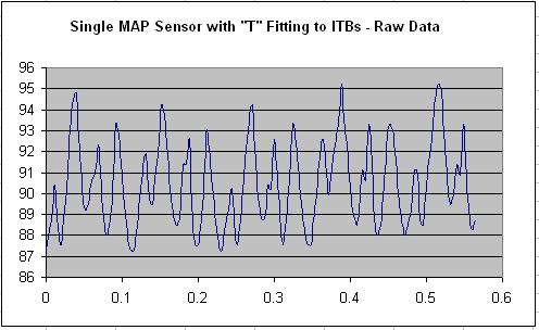
With the "T" arrangement the minimum MAP signal is roughly 87 kPa, maximum is 95 kPa. The MAP kPa range (ΔkPa) is 8 kPa.
The T signal is really just the average of all of the four pressures in each ITB along with some lag. But there is not a lot of dynamic response on the actual MAP pressures.
Now, the same setup but using the SynchroMAP™ where there is one MAP sensor per ITB and the lowest pressure signal is routed to the SynchroMAP™ output (the output feeds the ECU as the MAP signal):
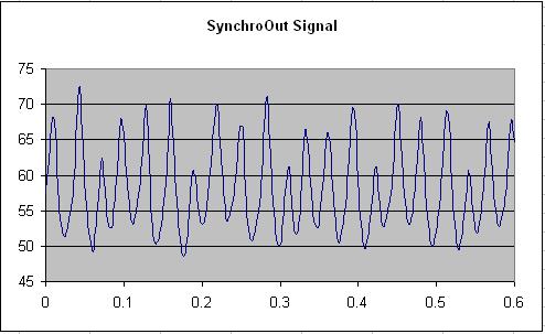
The maximum pressure is 73 kPa and the minimum pressure is 48 kPa - the delta pressure range (ΔkPa) is now 25 KPa. The important values are the minimums, with the "T" the MAP is 87 and with the SynchroMAP™ it is 48 kPa. This is nearly a 40 kPa pressure difference!
Bruce then captured each of the four MAP sensor signals on the SynchroMAP™:
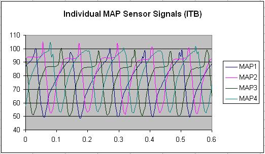
Interesting thing here is that the maximum KPa signals can exceed the 101 kPa atmospheric pressure. The other interesting thing to note is the minimums of each runner is not the same, this is due to differences in the throttle plate open area. You can see this on each drawn down cycle on each ITB. Bruce did not attempt to balance the ITBs on this engine, but with this data this is now a trivial thing to do.
Finally, Bruce made the assumption earlier that with a "T" fitting it acts as a simple average of the four ITB instantaneous pressures. With that, it should then be possible to use the four MAP sensor outputs from the above graph and generate the numeric average (correlated in time) and compare with the "T" output. With a simple equation in Excel here is the result:
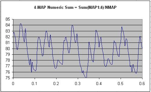
Really interesting! Compare this to the first plot above from the T arrangement. Although in this plot the pressures are lower than that of the "T" setup (minimum of 75 kPa compared to 87 kPa) the shape of the curves are very similar. It appears that the "T" setup adds in some additional averaging and/or lag, maybe due to signal transport effects on the narrow MAP hose. It may be possible to further average the 4-MAP signal to approach the "T" graph.
In conclusion, the SynchroMAP™, on this engine and condition, yields significantly increased MAP dynamic range compared to a simple "T" setup.